What Is the LPG Vaporizer Working Principle?
The industrial LPG vaporizer working principle is based on a simple but critical physical process: converting liquefied petroleum gas from its liquid state into a stable, usable gas by supplying controlled heat. In industrial environments, LPG is stored and transported as a liquid under pressure to save space. However, burners, boilers, furnaces, and process equipment require LPG in gaseous form. This is where vaporizers become essential.
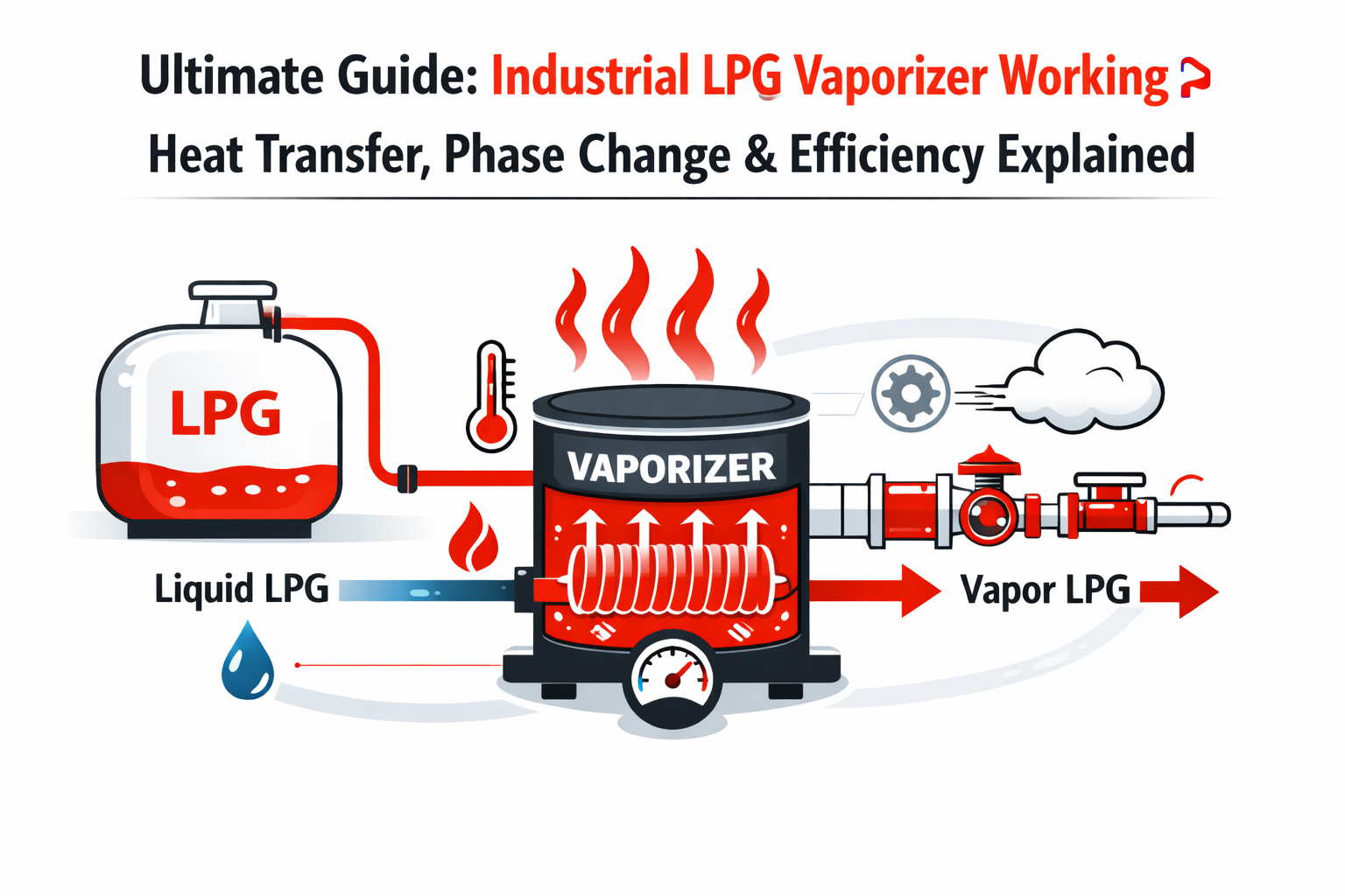
At its core, how an LPG vaporizer works is straightforward. Liquid LPG enters the vaporizer under controlled pressure. Inside the system, heat is transferred to the liquid through a designed heat source, such as electricity, hot water, or combustion gases. As LPG absorbs this heat, it undergoes a phase change—from liquid to vapour—and exits the vaporizer as dry, regulated gas ready for downstream use. The entire process is engineered to be stable, predictable, and safe, even under fluctuating demand.
This controlled approach is fundamentally different from natural vaporization. In small cylinders or low-demand setups, LPG can vaporise naturally by absorbing heat from the surrounding air. However, this method has clear limitations. As demand increases, the liquid LPG cools rapidly, reducing vapour pressure and gas flow. In colder conditions or high-consumption industrial operations, natural vaporization becomes unreliable. This comparison between vaporizer vs natural vaporization explains why industrial systems cannot depend on ambient heat alone.
In industrial LPG vaporizer working scenarios, the goal is not just to produce gas, but to do so consistently. Factories in high-demand zones—such as textile processing units, food manufacturing plants, and ceramic industries around Lahore—require uninterrupted gas flow throughout long operating cycles. Vaporizers ensure that gas production remains stable regardless of ambient temperature, cylinder size, or consumption spikes. This reliability is essential for process safety, product quality, and operational efficiency.
From a system perspective, an LPG vaporizer acts as a controlled energy exchange unit. Liquid LPG flows in, heat is applied in a regulated manner, and gaseous LPG flows out at the required pressure and temperature. A typical system flow diagram would show liquid LPG entering the vaporizer, passing through a heat exchange zone, and exiting as vapour into the gas distribution line. This visual representation helps engineers understand how phase change is managed without exposing the system to thermal stress or pressure instability.
Across Pakistan, especially in industrial clusters, properly designed vaporization systems are a core part of compliant LPG infrastructure. Suppliers such as Indus 3 support these installations by engineering complete industrial LPG systems in Pakistan that align with operational and regulatory needs. For facilities evaluating equipment configurations, understanding vaporization principles is just as important as selecting the right capacity or control method. You can explore relevant system categories under industrial LPG vaporizers at https://indus3.pk/shop-page/, while broader system context is available at https://indus3.pk/.
This section establishes the foundation of the LPG vaporizer working principle. In the following sections, the discussion will move deeper into heat transfer behaviour, phase change mechanics, system components, and safety controls—building a complete technical understanding step by step.
Thermodynamics of LPG Vaporization: Heat Transfer & Phase Change
Understanding the thermodynamics behind LPG vaporization is essential for designing safe and reliable industrial gas systems. While the science itself is well established, its real value lies in how it is applied inside an LPG vaporizer under operating conditions found in factories, processing plants, and boiler rooms.
At the centre of the process is LPG vaporizer heat transfer. LPG is stored as a liquid under pressure, even at normal ambient temperatures. To convert this liquid into gas, energy must be supplied in the form of heat. This energy does not raise the temperature of the LPG immediately. Instead, it is used to overcome intermolecular forces, allowing the liquid to change state. This required energy is known as latent heat. In practical terms, latent heat explains why LPG can absorb significant thermal energy during vaporization without a sudden rise in temperature.
This concept is critical in industrial systems. If heat were added too aggressively or unevenly, it could cause unstable vapor production or thermal stress on components. Modern vaporizers therefore apply heat gradually and uniformly, ensuring that the phase change happens in a controlled and predictable manner. This controlled input of energy is what separates engineered vaporization from uncontrolled boiling.
Another key factor is boiling point variation under pressure. LPG does not have a single fixed boiling point. As pressure increases, the temperature required for LPG to vaporise also increases. In industrial installations, LPG is often delivered at higher pressures to maintain flow stability. The vaporizer must therefore supply enough heat to match this elevated boiling point. This relationship between pressure and temperature is central to the LPG vaporiser phase transition explanation used by system designers and safety engineers.
In applied settings, vaporizers continuously balance three variables: incoming liquid flow, operating pressure, and available heat input. When these are correctly matched, the vaporizer gas production process remains stable, producing dry gas at consistent pressure. If demand rises suddenly, the vaporizer responds by transferring more heat to the incoming liquid LPG. If demand falls, heat input is reduced to prevent overheating or superheating of the gas.
A useful way to visualise this is through an illustrated phase-change diagram. Such a diagram typically shows liquid LPG entering the vaporizer, absorbing heat through a heat exchange surface, and gradually transitioning into vapour before exiting into the gas line. The emphasis is not on temperature spikes, but on energy absorption during the phase change itself. This visual helps operators understand why vaporizers rely on controlled heat transfer rather than direct flame contact or uncontrolled heating.
From an engineering standpoint, these principles are applied daily by teams with deep system-level experience. At Indus 3, more than 24+ years of LPG engineering expertise have gone into designing vaporization systems that respect these thermodynamic limits while meeting industrial demand across Pakistan. Their solutions are built around controlled heat exchange rather than brute-force heating, which improves reliability and operational safety.
For further technical validation, these principles align with established engineering references such as the GPSA Engineering Data Book, which details phase change behaviour and heat transfer considerations for hydrocarbon gases. Manufacturer technical manuals for industrial vaporizers also reinforce the importance of latent heat management and pressure-dependent boiling points in safe system design.
Facilities evaluating system layouts can explore heat exchanger-based LPG vaporizers to see how these thermodynamic principles are implemented in real equipment designs at https://indus3.pk/shop-page/. More background on Indus 3’s engineering approach is available at https://indus3.pk/about-us/.
With the thermodynamic foundation now clear, the next sections will break down how these principles are translated into physical components, system layouts, and operational controls within industrial LPG vaporizers.
Key Components of an Industrial LPG Vaporizer System
A stable and predictable gas output from an LPG vaporizer is not the result of a single component. It is achieved through a coordinated system where each element performs a specific mechanical or control function. Understanding these components helps engineers diagnose performance issues and design systems that remain reliable under varying load conditions.
At the heart of the system is the heat exchange assembly. The LPG vaporizer heat exchanger function is to transfer thermal energy from a controlled heat source into the liquid LPG stream. This is where the actual phase change takes place. The exchanger is designed to provide uniform heat distribution, preventing localised overheating while ensuring complete vaporization before gas exits the unit.
Within this assembly, the vaporizer heat exchanger coil role is particularly important. Liquid LPG flows through specially designed coils or tubing that maximise surface contact with the heat source. The coil geometry controls flow velocity and heat absorption time, ensuring the liquid absorbs sufficient energy to fully vaporise. Proper coil design also reduces pressure drop, which helps maintain steady downstream gas flow.
Heat exchangers are supported by inlet and outlet control valves that regulate how much liquid enters the vaporizer at any given time. These valves respond to system demand, opening or closing to match gas consumption. Their role is purely functional: they maintain balance between incoming liquid supply and outgoing gas demand, preventing starvation or flooding within the vaporizer body.
Equally critical is LPG vaporizer pressure regulation. Pressure regulators are positioned downstream of the vaporizer to stabilise gas pressure before it reaches burners or process equipment. Even when vaporization is complete, unregulated pressure fluctuations can disrupt combustion or process accuracy. Regulators smooth out these variations, ensuring consistent gas delivery regardless of upstream changes in supply pressure.
Sensors form the monitoring backbone of the system. Temperature sensors verify that sufficient heat is being transferred within the vaporizer, while pressure sensors confirm that gas output remains within safe operating limits. These sensors do not control the system directly but provide real-time feedback to control mechanisms or operators. In automated installations, sensor data is often linked to control valves or heat input systems to maintain equilibrium.
Safety-related components are integrated into this same framework. Relief valves protect against overpressure, while thermal cut-outs prevent excessive heating if flow conditions change unexpectedly. Although these elements are often passive, they are essential to maintaining stable operation under abnormal conditions.
For clarity, engineers often rely on a cutaway schematic illustration to visualise how these components interact. Such a diagram typically shows liquid LPG entering the coil, heat being applied through the exchanger wall, vapour forming within the coil, and regulated gas exiting through pressure control devices. This visual reinforces the idea that stability comes from system balance, not from any single part working in isolation.
In practical installations, these components are engineered as integrated assemblies rather than standalone parts. Suppliers offering complete LPG vaporizer systems design each element to work together under defined operating conditions. A broader overview of integrated system design can be found at https://indus3.pk/.
For those assessing equipment configurations or replacement parts, understanding individual functions is essential. Relevant industrial LPG vaporizer components can be explored in context at https://indus3.pk/shop-page/, where system-level compatibility is prioritised over isolated component selection.
With the mechanical roles of each component now established, the next sections will examine how different vaporizer designs arrange these elements to suit specific industrial applications and operating environments.
Types of LPG Vaporizers and Their Working Mechanisms
LPG vaporizers are classified by how heat is generated and controlled, not by capacity or branding. From an operational perspective, each type applies energy differently to achieve stable gas production. Understanding these differences helps engineers match vaporizer behaviour to load patterns, site conditions, and safety requirements—without assuming one design is universally superior.
Dry-Type LPG Vaporizer Working
Dry-type vaporizers rely on indirect heat transfer without immersing LPG in water or exposing it to flame. Heat is supplied through an internal exchanger—often electric or oil-heated—and transferred uniformly to the LPG flowing through coils or channels. The defining feature is tight heat control. Because there is no liquid bath, thermal response is quick and predictable, making dry-type units suitable for installations where demand fluctuates frequently.
Operationally, dry-type systems are compact and clean. They perform well in indoor settings where space is limited and environmental exposure must be minimised. Their control logic focuses on modulating heat input to match gas demand, reducing the risk of overheating or incomplete vaporization.
Water Bath LPG Vaporizer Principle
The water bath LPG vaporizer principle uses a heated water reservoir as the heat source. Liquid LPG passes through coils submerged in the bath, absorbing heat gradually from the surrounding water. The water acts as a thermal buffer, smoothing out short-term demand changes and providing stable vaporization over long operating cycles.
From an operational standpoint, water bath vaporizers are valued for thermal stability. They tolerate steady, high loads well and are less sensitive to rapid demand swings. However, they require ongoing water quality management and additional safety monitoring to ensure consistent bath temperature. These systems are often selected where continuous operation and thermal inertia are beneficial.
Direct-Fired LPG Vaporizer Working
In direct-fired LPG vaporizer working, heat is generated by a burner flame that transfers energy to the vaporizer’s heat exchange surfaces. This approach provides high heat intensity and rapid response, which can be advantageous in large industrial installations with substantial and consistent gas demand.
Operational control is more complex, as combustion must be carefully managed. Flame supervision, exhaust handling, and thermal shielding are integral to safe operation. Direct-fired units are typically installed in well-ventilated outdoor or semi-outdoor environments where combustion by-products can be safely managed. Their suitability depends heavily on site layout and regulatory compliance.
Electric LPG Vaporizer Working
Electric LPG vaporizer working is based on resistance heating elements embedded within or around the heat exchanger. Electrical energy is converted directly into heat, which is then transferred to the LPG stream. This method offers precise temperature control and clean operation, as there is no combustion or water medium involved.
Operationally, electric vaporizers are straightforward to automate and integrate into controlled environments. They are commonly used where electrical supply is reliable and emissions must be minimised. Their performance is closely tied to power availability, making electrical infrastructure a key consideration during system selection.
Operational Comparison and Application Suitability
A comparison diagram can be useful here, showing each vaporizer type mapped against its heat source, control method, and typical installation environment. Such a visual reinforces that selection is about application fit, not ranking.
Engineers evaluating options can review LPG vaporizer categories at https://indus3.pk/shop-page/ to understand how these designs are positioned for different operational needs. For site-specific guidance—particularly where safety constraints or load variability are involved—an industrial vaporizer consultation via https://indus3.pk/contact/ helps align vaporizer behaviour with real-world conditions.
The next section will examine how efficiency and operating conditions further influence vaporizer performance once a suitable type has been selected.
LPG Vaporizer Efficiency Factors and Operating Conditions
In industrial LPG systems, efficiency is not about achieving maximum output at all times. It is about producing gas consistently, safely, and predictably while using energy in a controlled manner. Understanding LPG vaporizer efficiency factors helps operators recognise how daily operating conditions influence system behaviour over time.
One of the most important factors is heat consistency. Vaporizers perform best when heat is applied evenly and steadily. Irregular heat input can lead to unstable vaporization, where gas quality fluctuates or liquid carryover becomes a risk. Consistent heat transfer allows LPG to complete its phase change smoothly, supporting reliable downstream pressure and combustion stability. From an operational standpoint, this means maintaining stable heat sources and avoiding abrupt start–stop cycles whenever possible.
Load matching is equally critical. Vaporizers are designed to operate within defined flow ranges. When gas demand aligns with the vaporizer’s operating window, heat input and LPG flow remain balanced. Problems arise when demand repeatedly exceeds or falls far below the expected range. Excessive load can strain heat transfer surfaces, while prolonged underloading can reduce thermal efficiency. Operators benefit from understanding typical consumption patterns and selecting operating modes that reflect real usage rather than peak assumptions.
Another often overlooked factor is insulation. Proper insulation around heat exchangers and piping reduces unwanted heat loss to the environment. Without adequate insulation, a portion of supplied energy is wasted, forcing the system to work harder to maintain vaporization. This does not immediately cause failure, but over time it affects operational stability and energy utilisation. Insulation quality becomes especially relevant in outdoor installations or facilities exposed to wind and temperature variation.
Ambient conditions also play a significant role. Surrounding air temperature influences how much supplemental heat a vaporizer must provide. In colder environments, more energy is required to achieve the same vaporization rate. Conversely, in warmer climates, the system may need less active heating. This is why LPG vaporizer operation temperature is managed as a range rather than a fixed value. Operators monitor temperature trends to ensure vaporization remains complete without overheating the gas.
A practical way to visualise these interactions is through a temperature control loop illustration. Such a diagram typically shows sensors monitoring gas temperature, a controller adjusting heat input, and feedback maintaining equilibrium. This loop demonstrates that efficiency is not static—it is continuously managed through feedback and adjustment rather than set once and ignored.
From a system perspective, efficiency is achieved when all these factors work together: stable heat input, appropriate load, effective insulation, and awareness of environmental influence. This operational mindset is central to industrial gas system optimisation, an approach refined through decades of field experience. More context on this engineering philosophy can be found at indus3.
For facilities reviewing equipment configurations, understanding efficiency behaviour helps inform better operational decisions rather than chasing nominal performance figures. Equipment designed with balanced heat transfer and control logic—such as high-efficiency LPG vaporizers—supports this stability-focused approach. Relevant system designs can be explored at our product page.
With efficiency drivers now clarified, the next section will focus on safety features and regulatory considerations that ensure these systems operate reliably under both normal and abnormal conditions
Safety Features and Regulatory Compliance in LPG Vaporizers
Safety is not an add-on in LPG vaporization systems; it is embedded into the design, control logic, and operational layout. Industrial installations handle pressurised, flammable media, which means LPG vaporizer safety features must function reliably under both normal and abnormal conditions. Each protective mechanism serves a defined role in preventing escalation from a fault into a hazardous event.
One of the primary safeguards is the pressure relief valve. This device protects the vaporizer and downstream piping from excessive internal pressure. If pressure rises beyond a preset limit—due to blocked outlets, abnormal heat input, or regulator failure—the relief valve opens automatically to discharge excess pressure in a controlled manner. This function is central to pressure regulation, ensuring that pressure excursions do not compromise mechanical integrity or create rupture risks.
Automatic shut-off systems form another critical layer of protection. These systems are designed to isolate the LPG supply when unsafe conditions are detected. Shut-off valves may be triggered by abnormal pressure, excessive temperature, power failure, or loss of flame in combustion-based vaporizers. By stopping the flow of liquid LPG at the source, the system prevents continued gas generation during fault conditions, limiting the scale of potential incidents.
In vaporizers that use combustion as a heat source, flame failure protection is mandatory. This mechanism continuously monitors the presence of a stable flame. If the flame is extinguished unexpectedly—due to fuel interruption, airflow disturbance, or ignition failure—the system immediately cuts off the fuel supply to the burner. This prevents unburned gas accumulation, which could otherwise lead to flashback or explosion when ignition resumes.
Alarm systems provide the critical interface between equipment and operators. Temperature alarms warn of overheating that could degrade seals or compromise vaporization stability. Pressure alarms alert operators to abnormal operating conditions before relief devices are activated. In automated installations, alarms may be linked to shutdown logic; in manual systems, they provide early warning so corrective action can be taken promptly.
These safety devices are typically arranged in a structured layout that prioritises fail-safe behaviour. A safety layout diagram often illustrates this clearly, showing how sensors feed into control units, how shut-off valves isolate the system, and where relief paths are directed. Such diagrams are used during commissioning, audits, and operator training to ensure safety logic is understood and respected.
Beyond mechanical safeguards, regulatory compliance defines how these systems must be designed and operated in Pakistan. The Oil and Gas Regulatory Authority (OGRA) establishes requirements for LPG installations, including vaporization systems, pressure vessels, and safety devices. Official guidance is available at OGRA. In parallel, the Petroleum and Explosives Safety Organisation (PESO) provides safety standards related to pressure equipment, hazardous installations, and fire prevention. Reference information can be accessed at peso.gov.
Compliance is not limited to equipment selection. It extends to documentation, inspection routines, and operator competency. Working with a regulated LPG system supplier ensures that vaporizer installations align with these regulatory expectations throughout their lifecycle. More information on Indus 3’s compliance-focused engineering approach can be found at experienced brand.
For facilities reviewing existing installations or planning new systems, obtaining LPG safety compliance guidance early in the design phase helps avoid retrofits and operational restrictions later. Technical consultation options are available at our trusted partner.
With safety and compliance mechanisms now outlined, the next section will focus on maintenance practices and long-term operational reliability, completing the practical picture of industrial LPG vaporizer management.
LPG Vaporizer Maintenance and Long-Term Performance
Reliable vaporizer operation depends as much on routine care as it does on design. In industrial settings, maintenance is not corrective by default; it is preventive. Clear inspection routines and early recognition of warning signs help protect equipment integrity, maintain gas quality, and reduce unplanned downtime. The following LPG vaporizer maintenance tips focus on practical actions operators can integrate into normal plant operations.
Routine Maintenance Practices
Daily and weekly checks are the foundation of vaporizer reliability. Operators should visually inspect external surfaces, insulation, and connections for signs of damage, corrosion, or heat loss. Any abnormal noise, vibration, or odour around the vaporizer should be investigated immediately. These observations often reveal developing issues before instrumentation thresholds are reached.
Heat transfer surfaces require particular attention. Over time, deposits, scale, or contaminants can reduce effective heat exchange, forcing the system to work harder to achieve the same gas output. Periodic cleaning—performed according to manufacturer guidance—helps maintain consistent vaporization behaviour. Electrical connections, where applicable, should be checked for secure terminals and signs of overheating.
Inspection Schedules and Functional Checks
Beyond routine observation, structured inspection schedules provide deeper assurance. Monthly inspections typically include verifying sensor calibration, checking valve actuation, and confirming pressure regulation performance. Relief valves and shut-off devices should be tested at defined intervals to ensure they respond correctly under simulated fault conditions.
Annual inspections often involve partial disassembly, internal inspection of coils or heat exchangers, and review of control logic. These checks are usually coordinated with planned shutdowns to minimise operational disruption. Maintaining accurate inspection records is essential, not only for reliability but also for compliance audits and safety reviews.
A maintenance checklist schematic can be helpful here. Such a schematic visually outlines inspection points—valves, sensors, relief devices, and heat transfer elements—ensuring no critical component is overlooked during routine servicing.
Recognising Performance Warning Signs
Many vaporizer issues develop gradually. One common warning sign is inconsistent outlet pressure, which may indicate fouled heat exchange surfaces or regulator drift. Slow response to demand changes can point to control valve wear or sensor inaccuracies. Temperature deviations—either persistent overheating or insufficient vaporization—often signal imbalance between heat input and LPG flow.
Operators should also watch for increased energy consumption without a corresponding increase in gas output. This pattern suggests declining thermal efficiency, often linked to insulation damage or internal fouling. Addressing these signs early reduces the likelihood of forced shutdowns or component damage.
Spare Parts and System Support
Timely replacement of worn components is a key part of preventive maintenance. Seals, sensors, and valves have finite service lives and should be replaced proactively rather than reactively. Access to compatible replacement vaporizer components supports this approach and helps maintain system continuity. Relevant component categories can be reviewed at indus3 shop.
Equally important is access to experienced technical guidance. When inspection findings are unclear or performance trends raise concern, consulting specialists familiar with industrial LPG systems helps avoid misdiagnosis. Facilities can seek technical LPG system support at indus3 to review operating data, inspection results, and corrective options.
With maintenance and performance management now covered, the final section will summarise the LPG vaporizer working principle as a complete system—linking thermodynamics, components, efficiency, safety, and upkeep into a cohesive operational understanding.
Understanding the LPG Vaporizer Working Principle: Final Insights
The LPG vaporizer working principle can be summarised as a controlled, engineered process that converts liquid LPG into stable, usable gas by applying regulated heat under defined pressure conditions. Liquid LPG enters the system, absorbs heat through a designed heat transfer mechanism, undergoes a phase change, and exits as vapour at a controlled pressure and temperature. Every part of this process is deliberate. Nothing is left to ambient conditions or chance.
This controlled vaporization is essential because LPG behaves differently at industrial scale than it does in small cylinders. Natural vaporization depends on surrounding air temperature and available surface area, which quickly becomes insufficient as gas demand rises. In contrast, vaporizers provide predictable gas production regardless of weather, duty cycle, or consumption peaks. This distinction explains why vaporizers are fundamental to modern industrial LPG systems rather than optional accessories.
Proper vaporization directly affects safety. Incomplete vaporization can lead to liquid carryover, unstable combustion, or pressure fluctuations downstream. Excessive or poorly controlled heating introduces its own risks, including material stress and overpressure. A correctly designed vaporizer balances heat input, flow rate, and pressure regulation so that LPG remains within safe operating limits throughout the process. This balance is supported by built-in safety devices, monitoring sensors, and shutdown logic, all working together as a single system.
Efficiency is another critical outcome of proper vaporization. When heat transfer is consistent and matched to demand, energy is used effectively rather than wasted compensating for instability. Stable vaporization supports uniform burner performance, predictable process temperatures, and reduced operational interruptions. Over time, this stability contributes to lower maintenance burden and more reliable plant operation, even though efficiency itself is never defined by a single metric.
Uptime is where these factors converge. Industrial facilities rely on continuous gas availability to keep production lines, boilers, and furnaces running. Vaporization problems often surface as unplanned shutdowns, inconsistent output, or repeated troubleshooting. By understanding and respecting the vaporizer working principle, operators can recognise early warning signs, apply correct operating practices, and maintain continuity across long operating cycles.
From a system perspective, vaporization should never be considered in isolation. It sits at the intersection of thermodynamics, mechanical design, control logic, safety compliance, and maintenance discipline. Each of the earlier sections—covering heat transfer, components, vaporizer types, efficiency drivers, safety features, and upkeep—connects back to this core principle: LPG must be vaporised deliberately, not incidentally.
For engineers and plant managers planning new installations or reviewing existing ones, aligning vaporizer design with real operating conditions is essential. This is where working with an experienced technical partner adds value. Indus 3 approaches LPG vaporization as part of a complete system, not as a standalone unit. Their broader work in industrial LPG infrastructure is outlined at indus3, providing context on system-level integration rather than isolated equipment supply.
Facilities seeking guidance on compliant layouts, operating margins, or upgrade paths can explore system options through shop or initiate a technical discussion via contact. These conversations are most effective when focused on application requirements, safety obligations, and long-term reliability rather than short-term fixes.
In closing, proper LPG vaporization matters because it underpins safe operation, stable performance, and sustained uptime. When the working principle is clearly understood and correctly applied, vaporizers become quiet enablers of industrial productivity rather than sources of operational risk.